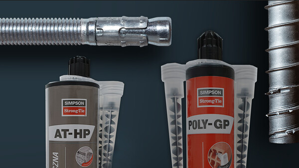
Resina para hormigón con altas prestaciones
La resina para cargas pesadas AT-HP conviene para fijar hierros y varillas roscadas en un hormigón fisurado y no fisurado y hormigones de C20/25 hasta C50/60.
Detalles de producto
Características
Materia
- Resina de metacrilato sin estireno
Ventajas
- Alto valor de adhesión en el hormigón y la mampostería
- Posible uso en agua potable: certificación WRAS
Aplicaciones
Soporte
Hormigón fisurado y no fisurado: M8 a M30
- Cargas estáticas y cuasiestáticas
- Hormigón seco o húmedo
Hormigón hierro Ø8 a Ø32
- Cargas estáticas y cuasiestáticas
- Exposición al fuego R180
Campos de aplicación
- Fijación de barandillas,
- Fijación de viseras,
- Extensiones de balcones,
- Vigas, pilares de hormigón...
Datos técnicos
Références
Modelo | Product information | ||||
---|---|---|---|---|---|
Grey color | Beige color | Content [ml] | Weight [kg] | Packaging qty [pcs] | |
ATHP300G-FR | x | - | 300 | 0.575 | 12 |
ATHP420G-FR | x | - | 420 | 0.828 | 12 |
Design resistance – Tension – NRd [kN] – hef = 8d – Carbon steel 5.8
Concrete :
1. The design loads have been calculated using the partial safety factors for resistances stated in ETA-approval(s). The loading figures are valid for unreinforced concrete and reinforced concrete with a rebar spacing s ≥ 15 cm (any diameter) or with a rebar spacing s ≥ 10 cm, if the rebar diameter is 10mm or smaller.
2. The figures for shear are based on a single anchor without influence of concrete edges. For anchorages close to edges (c ≤ max [10 hef; 60d]) the concrete edge failure shall be checked per ETAG 001, Annex C, design method A.
3. Concrete is considered non-cracked when the tensile stress within the concrete is\sigmaL +\sigmaR ≤ 0. In the absence of detailed verification\sigmaR = 3 N/mm² can be assumed (\sigmaL equals the tensile stress within the concrete induced by external loads, anchors loads included).
Design resistance – Tension – NRd [kN] – hef = 12d – Carbon steel 5.8
Concrete :
1. The design loads have been calculated using the partial safety factors for resistances stated in ETA-approval(s). The loading figures are valid for unreinforced concrete and reinforced concrete with a rebar spacing s ≥ 15 cm (any diameter) or with a rebar spacing s ≥ 10 cm, if the rebar diameter is 10mm or smaller.
2. The figures for shear are based on a single anchor without influence of concrete edges. For anchorages close to edges (c ≤ max [10 hef; 60d]) the concrete edge failure shall be checked per ETAG 001, Annex C, design method A.
3. Concrete is considered non-cracked when the tensile stress within the concrete is\sigmaL +\sigmaR ≤ 0. In the absence of detailed verification\sigmaR = 3 N/mm² can be assumed (\sigmaL equals the tensile stress within the concrete induced by external loads, anchors loads included).
Design resistance – Tension – NRd [kN] – hef = 8d – Stainless steel A4-70
Concrete :
1. The design loads have been calculated using the partial safety factors for resistances stated in ETA-approval(s). The loading figures are valid for unreinforced concrete and reinforced concrete with a rebar spacing s ≥ 15 cm (any diameter) or with a rebar spacing s ≥ 10 cm, if the rebar diameter is 10mm or smaller.
2. The figures for shear are based on a single anchor without influence of concrete edges. For anchorages close to edges (c ≤ max [10 hef; 60d]) the concrete edge failure shall be checked per ETAG 001, Annex C, design method A.
3. Concrete is considered non-cracked when the tensile stress within the concrete is\sigmaL +\sigmaR ≤ 0. In the absence of detailed verification\sigmaR = 3 N/mm² can be assumed (\sigmaL equals the tensile stress within the concrete induced by external loads, anchors loads included).
Design resistance – Tension – NRd [kN] – hef = 12d – Stainless steel A4-70
Concrete :
1. The design loads have been calculated using the partial safety factors for resistances stated in ETA-approval(s). The loading figures are valid for unreinforced concrete and reinforced concrete with a rebar spacing s ≥ 15 cm (any diameter) or with a rebar spacing s ≥ 10 cm, if the rebar diameter is 10mm or smaller.
2. The figures for shear are based on a single anchor without influence of concrete edges. For anchorages close to edges (c ≤ max [10 hef; 60d]) the concrete edge failure shall be checked per ETAG 001, Annex C, design method A.
3. Concrete is considered non-cracked when the tensile stress within the concrete is\sigmaL +\sigmaR ≤ 0. In the absence of detailed verification\sigmaR = 3 N/mm² can be assumed (\sigmaL equals the tensile stress within the concrete induced by external loads, anchors loads included).
Design resistance – Shear – VRd [kN] – hef = 8d – Carbon steel 5.8
Concrete :
1. The design loads have been calculated using the partial safety factors for resistances stated in ETA-approval(s). The loading figures are valid for unreinforced concrete and reinforced concrete with a rebar spacing s ≥ 15 cm (any diameter) or with a rebar spacing s ≥ 10 cm, if the rebar diameter is 10mm or smaller.
2. The figures for shear are based on a single anchor without influence of concrete edges. For anchorages close to edges (c ≤ max [10 hef; 60d]) the concrete edge failure shall be checked per ETAG 001, Annex C, design method A.
3. Concrete is considered non-cracked when the tensile stress within the concrete is\sigmaL +\sigmaR ≤ 0. In the absence of detailed verification\sigmaR = 3 N/mm² can be assumed (\sigmaL equals the tensile stress within the concrete induced by external loads, anchors loads included).
Design resistance – Shear – VRd [kN] – hef = 12d – Carbon steel 5.8
Concrete :
1. The design loads have been calculated using the partial safety factors for resistances stated in ETA-approval(s). The loading figures are valid for unreinforced concrete and reinforced concrete with a rebar spacing s ≥ 15 cm (any diameter) or with a rebar spacing s ≥ 10 cm, if the rebar diameter is 10mm or smaller.
2. The figures for shear are based on a single anchor without influence of concrete edges. For anchorages close to edges (c ≤ max [10 hef; 60d]) the concrete edge failure shall be checked per ETAG 001, Annex C, design method A.
3. Concrete is considered non-cracked when the tensile stress within the concrete is\sigmaL +\sigmaR ≤ 0. In the absence of detailed verification\sigmaR = 3 N/mm² can be assumed (\sigmaL equals the tensile stress within the concrete induced by external loads, anchors loads included).
Design resistance – Shear – VRd [kN] – hef = 8d – Stainless steel A4-70
Concrete :
1. The design loads have been calculated using the partial safety factors for resistances stated in ETA-approval(s). The loading figures are valid for unreinforced concrete and reinforced concrete with a rebar spacing s ≥ 15 cm (any diameter) or with a rebar spacing s ≥ 10 cm, if the rebar diameter is 10mm or smaller.
2. The figures for shear are based on a single anchor without influence of concrete edges. For anchorages close to edges (c ≤ max [10 hef; 60d]) the concrete edge failure shall be checked per ETAG 001, Annex C, design method A.
3. Concrete is considered non-cracked when the tensile stress within the concrete is\sigmaL +\sigmaR ≤ 0. In the absence of detailed verification\sigmaR = 3 N/mm² can be assumed (\sigmaL equals the tensile stress within the concrete induced by external loads, anchors loads included).
Design resistance – Shear - VRd [kN] – hef = 12d – Stainless steel A4-70
Concrete :
1. The design loads have been calculated using the partial safety factors for resistances stated in ETA-approval(s). The loading figures are valid for unreinforced concrete and reinforced concrete with a rebar spacing s ≥ 15 cm (any diameter) or with a rebar spacing s ≥ 10 cm, if the rebar diameter is 10mm or smaller.
2. The figures for shear are based on a single anchor without influence of concrete edges. For anchorages close to edges (c ≤ max [10 hef; 60d]) the concrete edge failure shall be checked per ETAG 001, Annex C, design method A.
3. Concrete is considered non-cracked when the tensile stress within the concrete is\sigmaL +\sigmaR ≤ 0. In the absence of detailed verification\sigmaR = 3 N/mm² can be assumed (\sigmaL equals the tensile stress within the concrete induced by external loads, anchors loads included).
Design resistance – Bending moment – MRd [Nm] – Concrete
Concrete :
1. The design loads have been calculated using the partial safety factors for resistances stated in ETA-approval(s). The loading figures are valid for unreinforced concrete and reinforced concrete with a rebar spacing s ≥ 15 cm (any diameter) or with a rebar spacing s ≥ 10 cm, if the rebar diameter is 10mm or smaller.
2. The figures for shear are based on a single anchor without influence of concrete edges. For anchorages close to edges (c ≤ max [10 hef; 60d]) the concrete edge failure shall be checked per ETAG 001, Annex C, design method A.
3. Concrete is considered non-cracked when the tensile stress within the concrete is\sigmaL +\sigmaR ≤ 0. In the absence of detailed verification\sigmaR = 3 N/mm² can be assumed (\sigmaL equals the tensile stress within the concrete induced by external loads, anchors loads included).
Design resistance – Tension – NRd [kN] – Rebar
Design resistance – Shear – VRd [kN] – Rebar
Design resistance – Bending moment – MRd [Nm] – Rebar
Instalación
Montaje
Tiempos de montaje
Temperatura del soporte | Duración práctica de uso | Tiempo de curado, (hormigón seco) tcur, seco | Tiempo de curado, |
0°C ≤ Tsoporte < +5°C | 25 min | 90 min | 3h00 |
5°C ≤ Tsoporte < +10°C | 17 min | 70 min | 2h20 |
10°C ≤ Tsoporte < +20°C | 12 min | 65 min | 2h10 |
20°C ≤ Tsoporte < +30°C | 6 min | 60 min | 2h00 |
30°C ≤ Tsoporte < +40°C | 3 min | 45 min | 1h30 |
Métodos de perforación
Ladrillo macizo / hormigón | Perforación por percusión |
Ladrillo hueco | Perforación rotativa |
Hormigón celular | Perforación por percusión |